Build an ESP32 RFID Attendance System with RC522, Buzzer & RGB LED
Attendance tracking is one of the most common and practical problems that IoT can solve beautifully. In this tutorial, you will build a fully working RFID-based attendance system using an ESP32 microcontroller, an RC522 RFID reader, an RGB LED for visual feedback, and a buzzer for audio feedback.
When a registered card or tag is scanned, the system lights up green and beeps once — access granted. An unregistered card triggers a red light and a different tone — access denied. The ESP32 logs each scan, making it straightforward to extend into a full network-connected attendance tracker.
This project is great for students learning embedded systems, hobbyists exploring IoT, and developers looking for a practical hardware-software integration example.
What You Need
MFRC522 library in Arduino IDE via Sketch → Include Library → Manage Libraries. Search for "MFRC522" by GithubCommunity.
Video Tutorial
Watch the full build walkthrough below. The video covers hardware setup, wiring, programming the ESP32, and a live demonstration of the attendance system in action.
Full build walkthrough by Codezlab on YouTube
How It Works
The RC522 communicates with the ESP32 over SPI (Serial Peripheral Interface) — a fast, short-distance protocol that uses four main lines: MOSI, MISO, SCK, and SS (SDA).
Here is the basic flow of the system:
- Card detected — The RC522 constantly checks for a card in its RF field. When one is found, it reads the unique UID (4–7 bytes).
- UID check — The ESP32 compares the scanned UID against a list of authorised UIDs stored in the code.
- Feedback — If the card matches, the RGB LED turns green and the buzzer beeps once (short). If no match, the LED turns red and the buzzer beeps twice (long).
- Serial log — Each scan is printed to the Serial Monitor with the UID and result, which you can extend to Wi-Fi logging or an LCD screen.
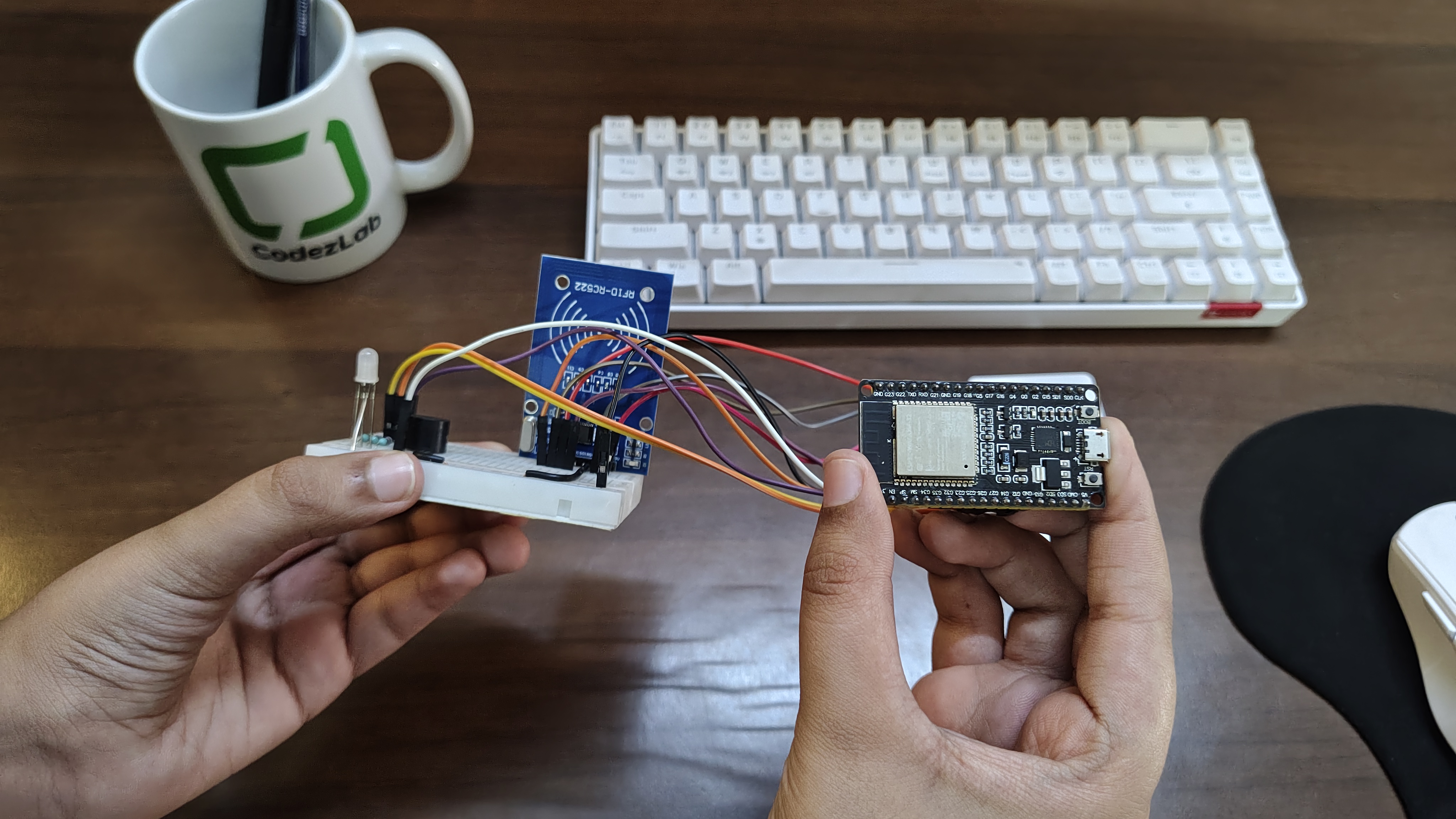
Wiring Diagram
Connect your components according to the diagram below. Double-check all connections before powering on — incorrect wiring of the RC522 can damage the module.
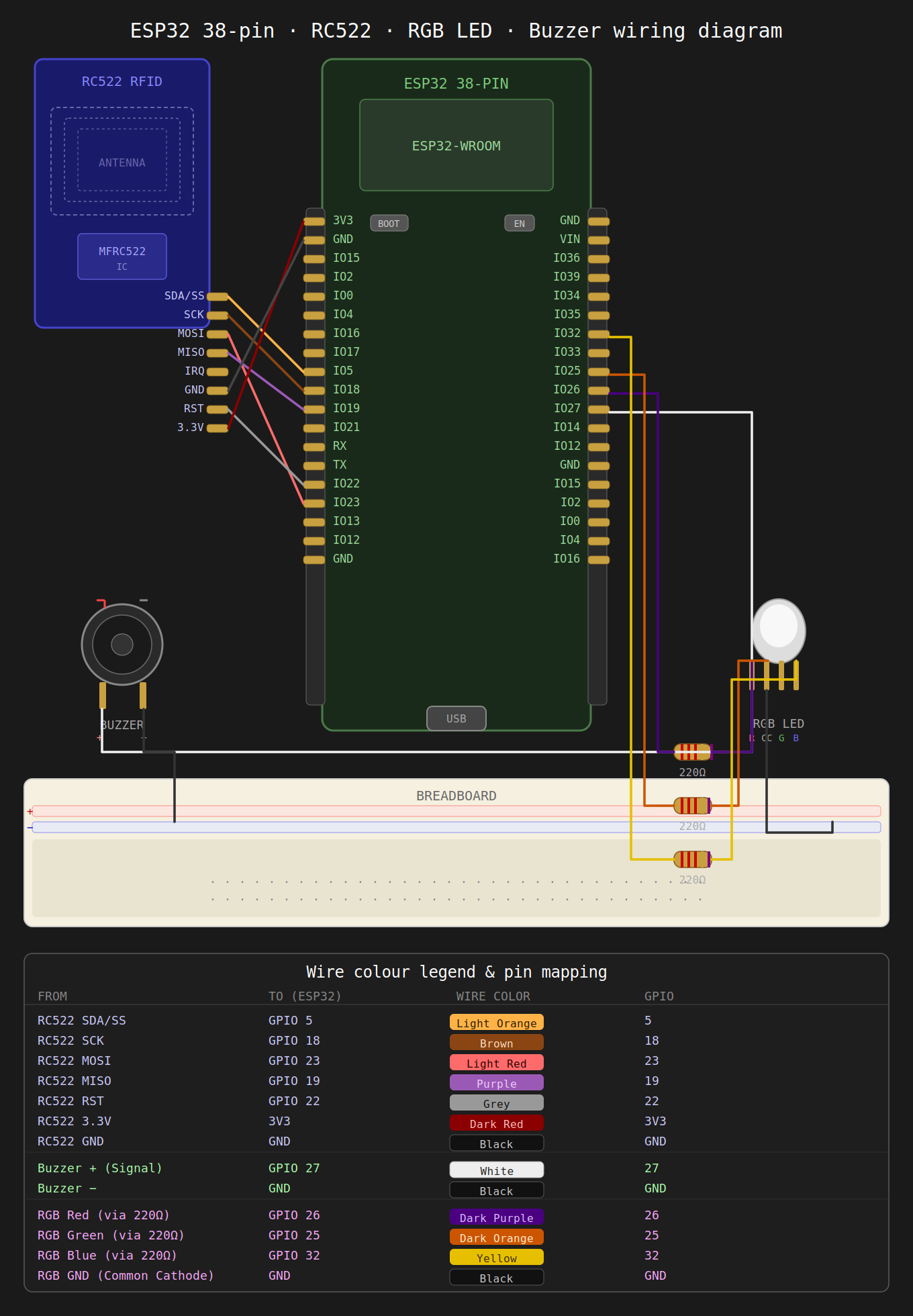
RC522 → ESP32 Pin Map
RGB LED & Buzzer → ESP32
The Code
Upload the following sketch to your ESP32 using Arduino IDE. Make sure you have selected the correct board (ESP32 Dev Module) and COM port before uploading.
#include <SPI.h>
#include <MFRC522.h>

#define SS_PIN     5
#define RST_PIN    22
#define BUZZER_PIN 27

#define RED_LED_PIN   26
#define GREEN_LED_PIN 25
#define BLUE_LED_PIN  32

MFRC522 rfid(SS_PIN, RST_PIN);

// Add your RFID card UIDs here
String allowedUIDs[] = {
  "17 C4 7F 05",
  "C1 82 74 A1",
};

// Student/User names according to UID order
String userNames[] = {
  "Person 1",
  "Person 2",
};

int totalUsers = 2;

void setup() {
  Serial.begin(115200);

  SPI.begin(18, 19, 23, SS_PIN);
  rfid.PCD_Init();

  pinMode(BUZZER_PIN, OUTPUT);
  digitalWrite(BUZZER_PIN, LOW);

  pinMode(RED_LED_PIN, OUTPUT);
  pinMode(GREEN_LED_PIN, OUTPUT);
  pinMode(BLUE_LED_PIN, OUTPUT);

  Serial.println("=================================");
  Serial.println(" ESP32 RC522 RFID Attendance System");
  Serial.println("=================================");
  Serial.println("Scan your RFID card...");
}

void loop() {
  if (!rfid.PICC_IsNewCardPresent()) {
    return;
  }

  if (!rfid.PICC_ReadCardSerial()) {
    return;
  }

  String scannedUID = getUID();

  Serial.println("---------------------------------");
  Serial.print("Card UID: ");
  Serial.println(scannedUID);

  int userIndex = findUser(scannedUID);

  if (userIndex >= 0) {
    Serial.print("Attendance Marked: ");
    Serial.println(userNames[userIndex]);
    Serial.println("Status: PRESENT");

    successGlow();
    successTone();
  } else {
    Serial.println("Unknown Card");
    Serial.println("Status: ACCESS DENIED");

    errorGlow();
    errorTone();
  }

  Serial.println("---------------------------------");

  rfid.PICC_HaltA();
  rfid.PCD_StopCrypto1();

  delay(1500);
  ledOff();
}

String getUID() {
  String uid = "";

  for (byte i = 0; i < rfid.uid.size; i++) {
    if (rfid.uid.uidByte[i] < 0x10) {
      uid += "0";
    }
    uid += String(rfid.uid.uidByte[i], HEX);
    if (i < rfid.uid.size - 1) {
      uid += " ";
    }
  }

  uid.toUpperCase();
  return uid;
}

int findUser(String uid) {
  for (int i = 0; i < totalUsers; i++) {
    if (uid == allowedUIDs[i]) {
      return i;
    }
  }
  return -1;
}

// ── LED functions ────────────────────────────────────────

void ledOff() {
  digitalWrite(RED_LED_PIN, LOW);
  digitalWrite(GREEN_LED_PIN, LOW);
  digitalWrite(BLUE_LED_PIN, LOW);
}

void successGlow() {
  digitalWrite(RED_LED_PIN, LOW);
  digitalWrite(GREEN_LED_PIN, HIGH);
  digitalWrite(BLUE_LED_PIN, LOW);
}

void errorGlow() {
  digitalWrite(RED_LED_PIN, HIGH);
  digitalWrite(GREEN_LED_PIN, LOW);
  digitalWrite(BLUE_LED_PIN, LOW);
}

// ── Buzzer functions ─────────────────────────────────────

void successTone() {
  tone(BUZZER_PIN, 1000, 150);
  delay(180);
  tone(BUZZER_PIN, 1500, 150);
  delay(180);
  tone(BUZZER_PIN, 2000, 200);
  delay(220);
  noTone(BUZZER_PIN);
}

void errorTone() {
  tone(BUZZER_PIN, 400, 250);
  delay(300);
  tone(BUZZER_PIN, 300, 250);
  delay(300);
  noTone(BUZZER_PIN);
}
Testing Your Build
- Open Serial Monitor at 115200 baud after uploading.
- Scan your registered card — you should see a green flash and one short beep.
- Scan an unregistered card — you should see a red flash and two long beeps.
- Check the Serial Monitor output for the scanned UID and access result on each scan.
If the RC522 is not detected, power-cycle the ESP32, confirm your wiring matches the pin table above, and ensure the library is correctly installed.
Next Steps
Once the basic system is working, here are some practical extensions:
- Wi-Fi logging — Send scan data to a Google Sheet via Google Apps Script or to a Firebase Realtime Database.
- LCD display — Add a 16×2 I2C LCD to show the cardholder's name and timestamp locally.
- EEPROM storage — Store registered UIDs in EEPROM so they persist across power cycles without re-uploading the sketch.
- Relay control — Connect a relay to a door lock or turnstile to make the system physically control access.
- Web dashboard — Build a small Express.js or Flask server that receives attendance pings and shows a live dashboard.